Principe de fonctionnement
Les vibrations et les chocs peuvent rapidement altérer l'étanchéité du joint et affecter les performances globales du produit.
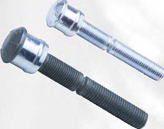
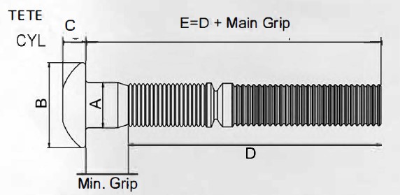
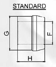
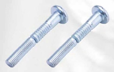
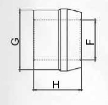
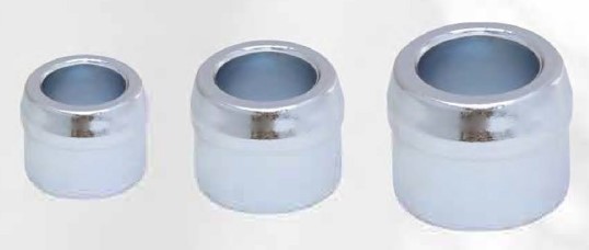
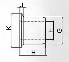
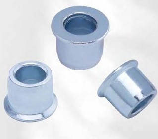
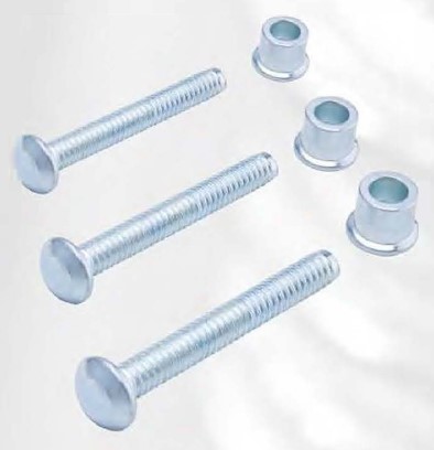
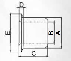
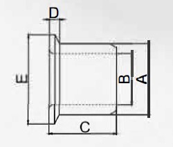
En fixant avec Pl Lockbolts, vous êtes assuré d'une connexion hautement résistante aux vibrations. Le collier est serti dans les rainures de verrouillage annulaires du boulon de verrouillage, formant un verrou permanent avec des valeurs de serrage, de traction et de cisaillement uniformes.
L'installation est simple, rapide et pratiquement infaillible même avec du personnel non qualifié.
Pl Lockbolts réduisent les coûts d'installation et améliorent la qualité et la fiabilité du produit. L'essayer c'est l'adopter. Demandez une démonstration pour apprécier pleinement ce remarquable système de fixation.
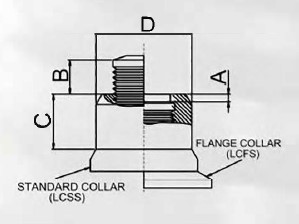
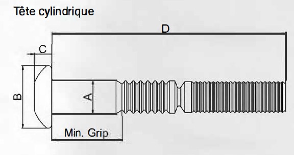
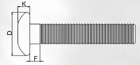
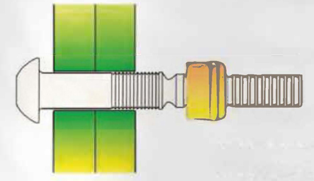
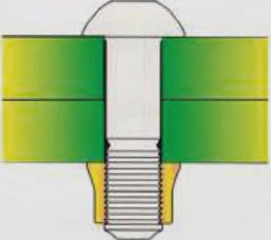
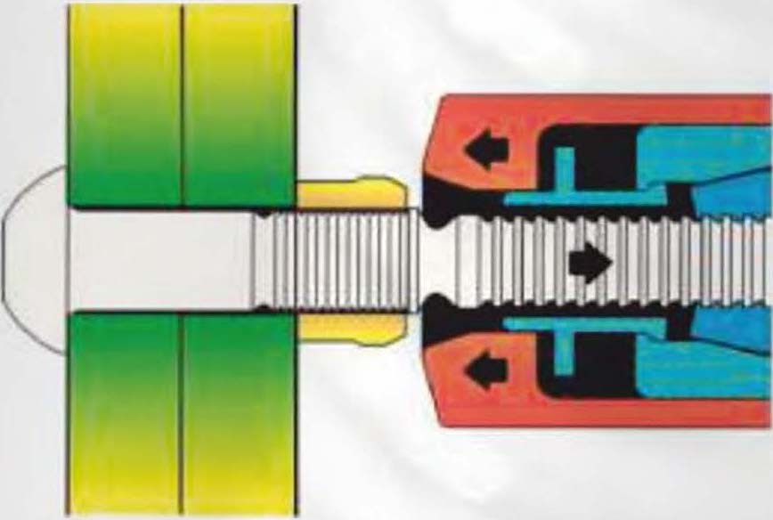
La goupille du boulon de verrouillage est insérée dans le trou d'assemblage et la bague est placée sur la tige d'assemblage. Lorsque l'outil d'installation est activé, il tire sur la goupille et l'enclume de sertissage force la bague contre l'assemblage, resserrant les éléments ensemble.
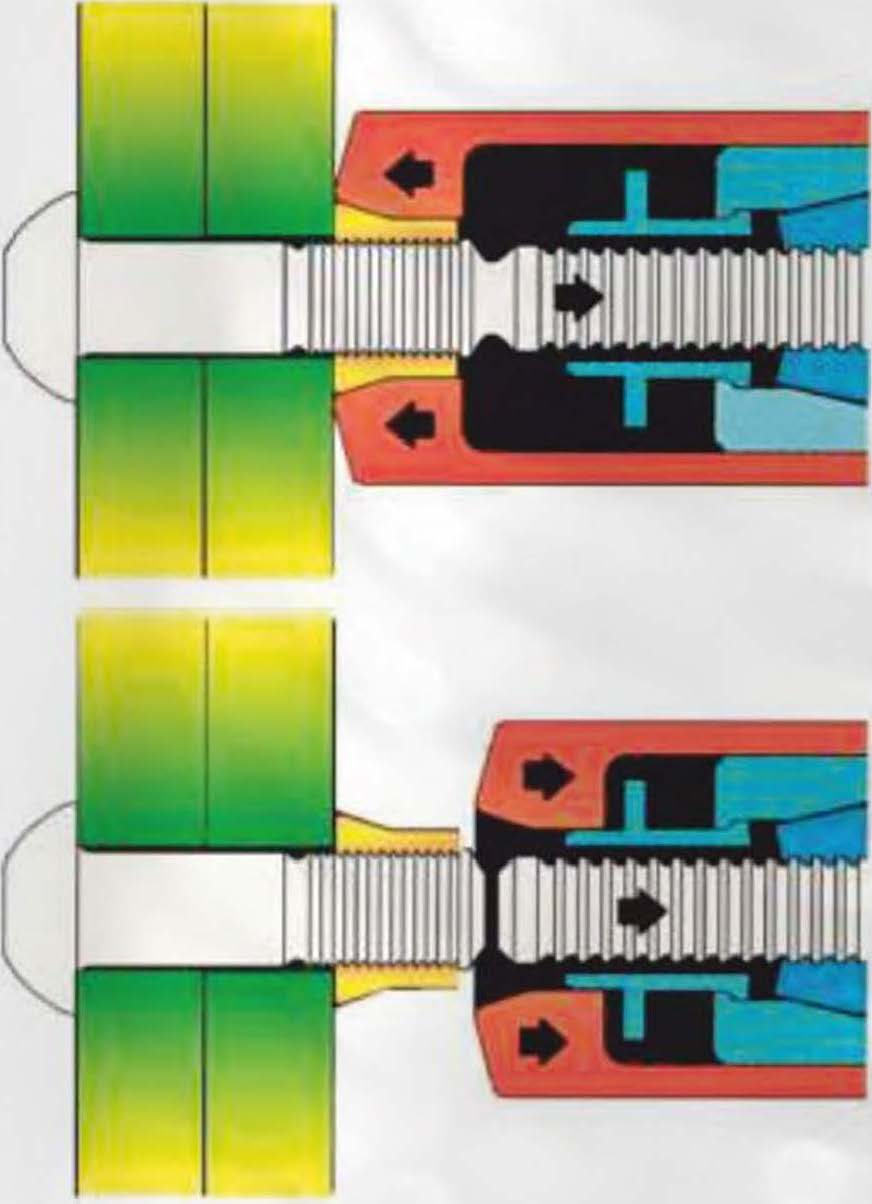
Au fur et à mesure que la traction sur la goupille augmente, l'enclume de sertissage se déplace sur la bague, la pressant dans les rainures de verrouillage annulaires.
L'accumulation continue de forces opposées par l'outil d'installation provoque la rupture de la goupille au niveau de la gorge de rupture. Le cycle de l'outil d'installation est alors inversé, ce qui fait que le déverrouillage intégré et l'éjecteur poussent l'outil hors de la fixation installée. Un sertissage complet est suffisant pour assurer un serrage parfait.
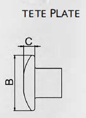
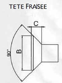
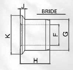
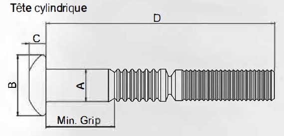
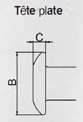
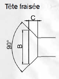
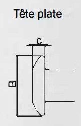
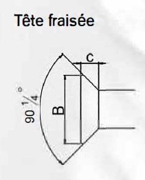
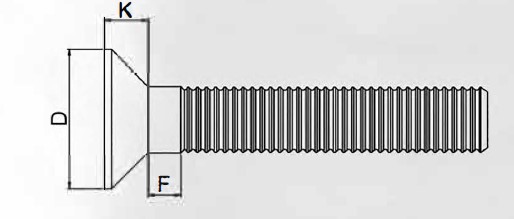
Les boulons de verrouillage installés, quel que soit le style de tête, fournissent une fixation robuste et résistante aux vibrations, avec une plus grande économie que celle obtenue avec d'autres méthodes.